
IB Induction
Page 1
1. There are several ways to induce an e.m.f. in a conductor. Which one of these will not work?
|
|||||||||||||||||
2. The magnetic flux cutting through a loop of wire is defined as ...
|
|||||||||||||||||
3. Which of these is the unit for magnetic flux?
|
|||||||||||||||||
4. "The direction of the induced current in a conductor will be in such a direction so as to oppose the change in flux that created it." This law is called ...
|
|||||||||||||||||
5. The magnitude of the e.m.f. induced in a conductor is proportional to ...
|
|||||||||||||||||
| 6+7. The diagram shows a long wire placed in a magnetic field directed in to the screen. | 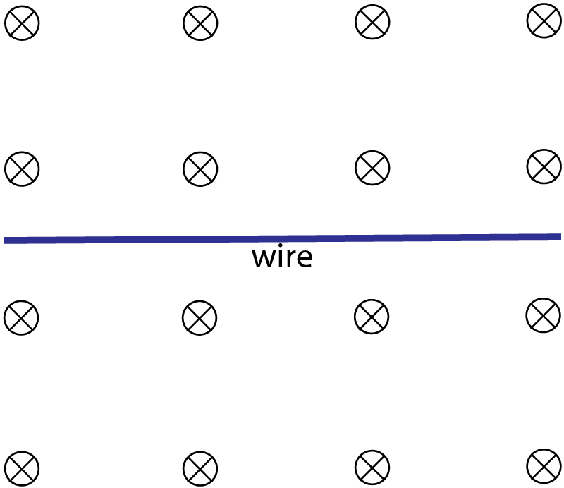 |
||||||||||||||||
6. Which of these answers correctly describes the direction of the induced current in the wire when it is moved upwards (up the screen), or moved to the right?
|
|||||||||||||||||
7. In the above diagram, If the field strength is B and the wire of length l is moved with a velocity v, the maximum induced e.m.f. will be E. The experiment is repeated with a shorter wire of length l/4 and moved at a velocity of 3v. To induce the same e.m.f. E in the wire the magnetic field strength must be:
|
|||||||||||||||||
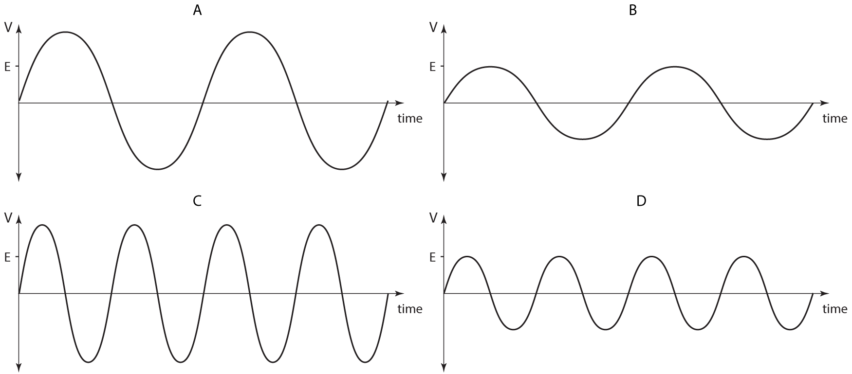
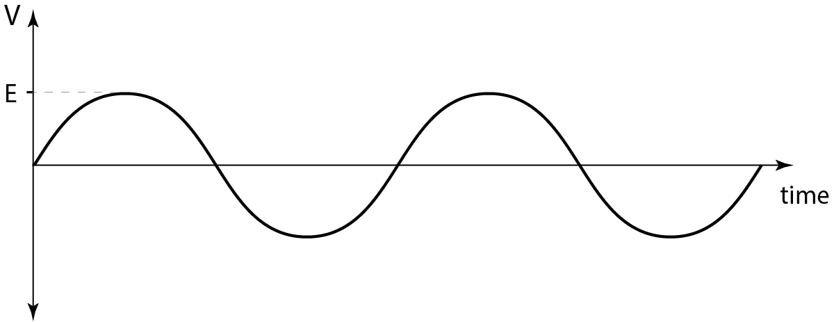
8+9. A coil is rotated at a constant frequency f inside a magnetic field. The induced e.m.f. generated in the coil is shown in this diagram. The peak e.m.f. is E. |
 |
||||||||||||||||
8. Which of these four graphs shows the induced e.m.f. when the coil is rotated at a frequency of 2f?
|
|||||||||||||||||
| 9. The r.m.s. voltage induced in this coil when rotated at the higher frequency of 2f is:
A. 2E B. E√2 C. E
|
|||||||||||||||||